header photo

Thursday, December 15, 2011

Z axis almost done!

I have not posted in a while, but I have been making progress! The lead screws fit the skate board bearings nicely so I decided to cut two ends with pockets for the skateboard bearings.


I had to play with the tolerances to get a nice press fit of the bearing into the ends. The ends turned out really nice!


Now I just need to attach the lead screw nut to the carriage, figure out how to attach the stepper motor, and create mounts to hold the tool.

For the tool, I am thinking about upgrading my Dremel to the Craftsman professional palm router so that I can use 1/4" end-mills and have more power!

Saturday, November 12, 2011

Lead Screws!

I recently bought and received three lead screws from precisiontechmachining on ebay. I got two 18in and one 24in long 3/8-16 lead screws. They each came with a delrin nut which seems to work nicely. Unfortunately, the 24in one seems to have been damaged in the mail. I am trying to see if they will replace it.


It fits nicely between my linear bearing rails!


The ends are turned 5/16in. The 6mm ID skateboard bearings I have fit snugly. I might have to invest in angular contact bearings though.


The damaged 24in screw. It is not bad however it could cause significant whipping.

Sunday, September 25, 2011

V2.0 3D Model Continued, Theory Tested

I found some time this weekend to continue the development of my new and improved V2.0 CNC machine. Unfortunately, with my current machine I am unable to cut some of the pieces of V2.0 so I had to divide those pieces into smaller pieces that my current machine can handle. Check it out! Let me know what you think!


I used my existing CNC machine to cut out one of the bearing pieces to see how my machine does and see how the bearing concept works. It actually turned out fairly well. There is some play in the bearings however I think that I can adjust the bearings to eliminate the play. So far so good!


Thursday, September 15, 2011

Backlash Fixed! Conceptual 3D model Started

I fixed the backlash in my v1.0 machine. It turned out to be as simple as adding another bolt to my lead screw nut to keep the nut from turning while applying a force to it. I re-cut the test pattern and my machine seems to have no more backlash, well at least no significant backlash.

So, I started drawing up the 3D model of my next machine. This design will be significantly more rigid by using the 3/8" steel V groove bearings and aluminum or steel extrusions for the rails. Check out the Z and Y axes:


I am having trouble figuring out how to support the ends of the Y axis. Any Ideas?

Wednesday, August 31, 2011

Backlash, Version 2.0 Design Concept

So I have backlash! I did not know how to measure it until I posted over on the 
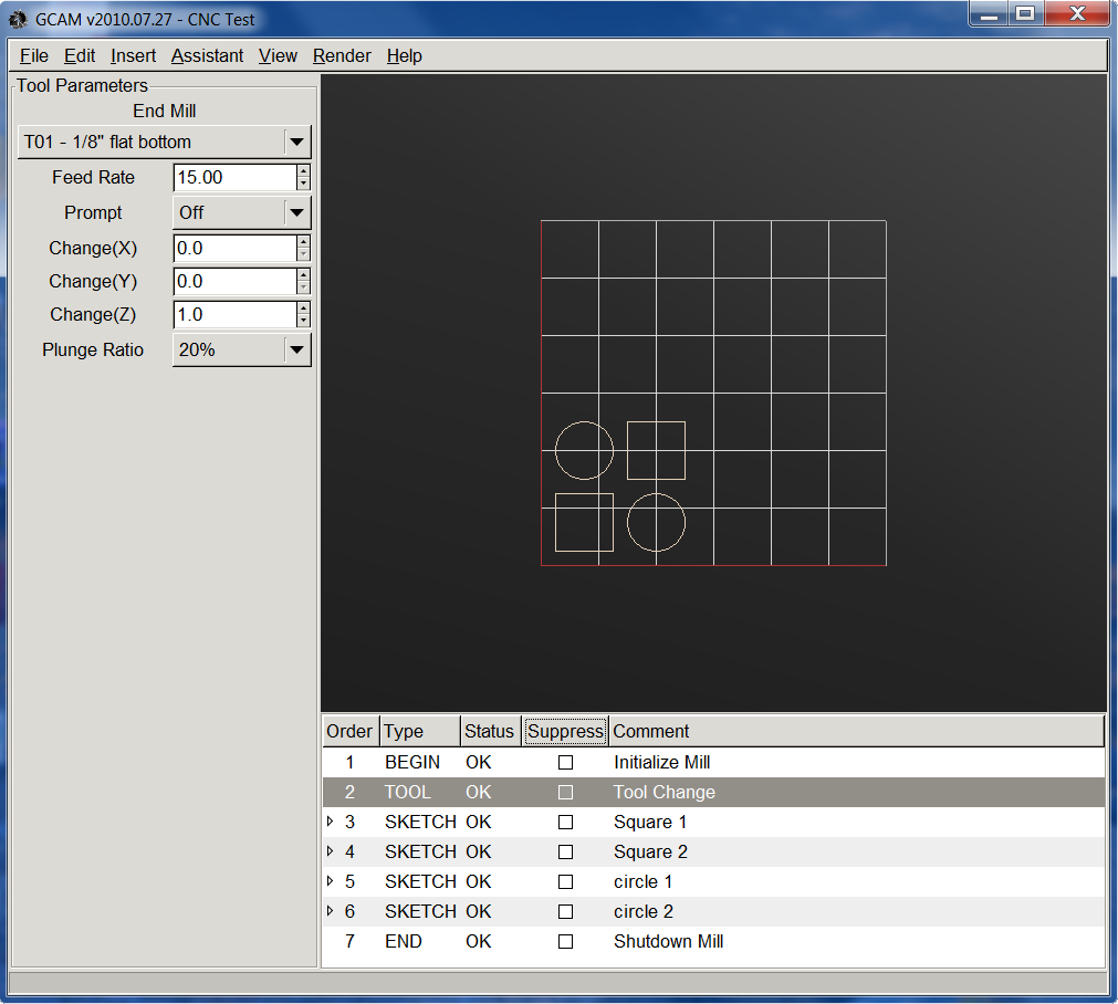
CNCZonne. It was suggested that I cut a pattern in an attempt to figure out my backlash problems.

Backlash measurement pattern.

So I cut out he piece and measured it. It turns out that I have zero backlash in the Y direction, however I have 0.0155in of backlash in the X direction. I then examined my machine and found the cause to be my lead screw nut. It seems to have significant play. I will have to make another nut and see if that eliminates my problems.

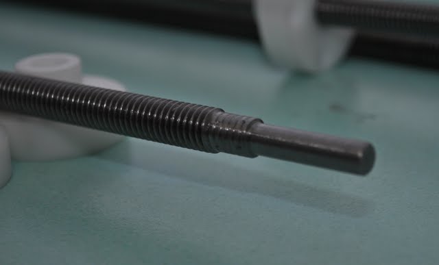
backlash test piece, two 1" squares joined together.


I also have been working on a proof of concept for my next machines linear bearings. As I said int he previous post, I recently bought 3/8" V groove bearings. I used my CNC machine to cut out two end pieces out have a cutting board to hold 3/4" aluminum square tubing. It seems that this concept will work well! The two aluminum rails are extremely parrellel, only varying from one end to the other by a few thousandths of an in! If I correct that backlash problem I have, it could be even better!


This new machine is going to be awesome!

Wednesday, July 20, 2011

Workbench/Plans for CNC V2.0?

So, I have moved recently and finally have built myself a proper work bench to set up my CNC machine on, instead of the floor! Check it out, it is nice!


Also, I have been working on plans for my next machine! I am planning on using 3/8" steel V-groove bearings for the linear motion system, which I just happen to win 16 of them off Ebay! I am currently working on a drawing and will post it when I have completed it. They should defiantly be better then skate-board bearings!

Thursday, July 7, 2011

Fishy!

Just for fun, and to prove to my fiance that the machine could make cool things, I drew a fish in GCAM and generated the gcode. Check it out!


Monday, June 27, 2011

First Part: Arduino Prototyping Board with video!

I decided to make my first part! I recently got an Arduino Uno to start playing with and eventual use to make something cool! Anyway, I wanted a simple prototyping platform so I used GCAM to generated some gcode to cut a piece of cutting board that I could mount the Arduino on and a small prototyping board. I actually managed to cut the part with no problems on my first try! Check it out.


Wednesday, June 22, 2011

Precision! Kinda.

So now that I got the Dremel cutting things, I decided to test the accuracy of my machine by cutting 1in squares and circles.  I ended up cutting six circles and seven squares. The squares are surprisingly square and the circles are not quite perfect circles, but they are close. So the end result for my accuracy test:

Squares: 0.9818 +/- 0.01729 in
Circles:  0.9720 +/- 0.02246 in
 
I might be able to compensate somewhat with software. I can guarantee that my 1/8" end mill is cutting slightly larger then 1/8", resulting in slightly smaller squares and circles.


I used GCAM to create the G-Code for the test.

Time to make some real parts!

Sunday, June 12, 2011

It's Dremel Time! (& Video)

So I mounted my Dremel 4000 to my Z-axis with some U bolts and miscellaneous pieces of aluminum extrusion. It is actually pretty ridged.


I am currently in the process of moving so it might take a while before I get up and running at my new apartment.

Tuesday, May 24, 2011

Video of Testing!

I borrowed my fiancee's video camera and filmed my CNC machine drawing the snowflake example in EMC2 as well as the letters "GCAM" which I made using GCAM.

Tuesday, May 17, 2011

Testing continued (Pen)

Today I continued to test my machine with examples built into EMC2 and simple gcode generated by GCAM. I am fairly impressed with the abilities of this machine made from junk I got off ebay and junk from lowes.

Snowflake example.
The J and the circles I made in GCAM.
Close-up of the snowflake.

Tuesday, May 10, 2011

First Test (Pen)

I made a holder for a ball point in order to test my machine by drawing instead of cutting. I am surprised that the darn thing actually works! Although, I can tell that my table is not level since the pen will write in some places, but others it will not write, or even press to hard and rip the paper. Hopefully some tuning will solve these issues.


Monday, May 9, 2011

Z Axis Works!

Today I got the Z axis working! I used the same basic design as the other axes except I "flipped" it around. The Stepper motor moves with the tool and rails. Hopefully pictures explain it better.

I used 7 skateboard bearings to hold the axis.
Closeup of the bearings.
The nut is fixed to the frame so the stepper motor, rails and eventual tool move together.
All the axes together!

All connected and ready for testing!

Monday, April 25, 2011

Y Axis Works!

I finally finished the Y-axis. Same basic design as the X-axis, aluminum U-channels for the rails, skateboard bearings to ride the rails, 1/4-20 lead screw, custom built anti-backlash nut, and stepper motor. Ran both axises with the EMC2 logo built in G-code. Both axises work fine, although there is some flex in the X-axis rails as the Y-axis moves around.

X & Y axis

Bottom of Y Axis
Skateboard bearings, ride aluminum rail.
Ant-Backlashnut.
Stepper motor.

Now it is time to get going on the Z axis!

Thursday, March 17, 2011

X Axis Works!

I managed to mount the stepper motor for the X axis and connect it to the lead screw with the flex couplings I got off eBay.


After running the X axis back and forth and running through the EMC2 default G-code, I realized that I am going to need bearings to keep the nylon sheet from lifting off the rails. So, I built two bearings.

Two bearings on the underside, catercorner to each other.

Same design as the other bearings.


I also started working on the Y-axis and once again, the nylon sheet is not flat so I have to add tubing to flatten the sheet.

Close up of Y-axis bearings